
Page 10 - Paladin Healthcare LLC - JSN Catalog
P. 10
EVOLUTION:
RAIL INSTALLATION INSTRUCTIONS
1. When rails are mounted in accordance to manufacturer’s installation instructions, rail shall accommodate
function loading up to 62-foot pounds of torque per foot between 16” centers.
2. The recommended Evolution Equipment Rail loading should not exceed 20 pounds of weight per linear foot.
3. The Evolution Equipment Rail loading capability is as well a function of dry wall load bearing capacity, drywall
mounting/installation, and quality of installation hardware.
** Installer MUST use 1/4” mounting hardware appropriate to wall construction type or to
the installation method required.
Contact manufacturer with any installation questions at (407) 614-8781
** Refer to the relevant elevation drawings and other specification documentation for
quantity and location details for each project.
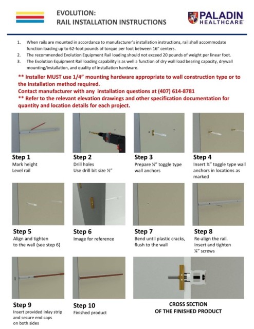
Step 1 Step 2 Step 3 Step 4
Mark height Drill holes Prepare ¼” toggle type Insert ¼” toggle type wall
Level rail Use drill bit size ½” wall anchors anchors in locations as
marked
Step 5 Step 6 Step 7 Step 8
Align and tighten Image for reference Bend until plastic cracks, Re-align the rail.
to the wall (see step 6) flush to the wall Insert and tighten
¼” screws
10
Step 9 Step 10 CROSS SECTION
Insert provided inlay strip Finished product OF THE FINISHED PRODUCT
and secure end caps
on both sides